
Industrial processes – from cement production to pharmaceutical manufacturing-produce airborne dust that can compromise air quality, worker safety, and equipment efficiency.
To manage this challenge, industries rely on one of the most effective air filtration technologies available: the pulse jet dust collector.
This system is widely used because it offers continuous cleaning, minimal maintenance, and high filtration efficiency even in demanding environments.
How a Pulse-Jet Dust Collector Works
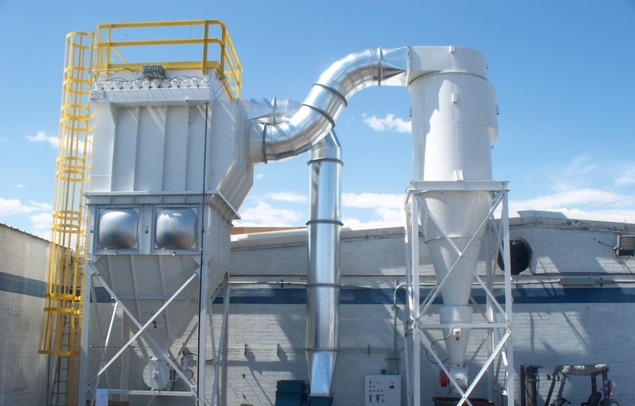
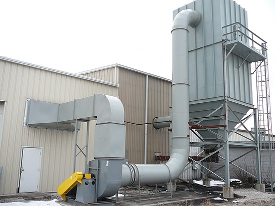
At its core, a pulse jet dust collector is a filtration device that separates dust particles from an airstream using fabric filter bags (or cartridges) and compressed air pulses to clean them. The working principle revolves around three key stages: filtration, cleaning, and dust discharge.
- Filtration: Dust-laden air enters the collector housing through an inlet duct. Larger particles immediately settle due to reduced velocity, while finer particles are captured on the surface of the filter bags as clean air exits through the outlet. Over time, a “dust cake” forms on the bags, which actually helps improve filtration performance-up to a point.
- Cleaning: When differential pressure (pressure drop across the filter) reaches a set limit, a pulse of compressed air is released through a blow tube positioned above each row of bags. This short, high-pressure burst expands the filter bags, dislodging accumulated dust.
- Dust Discharge: The dislodged dust falls into a hopper at the base of the collector, from where it can be removed via a screw conveyor or rotary valve.
This automated cleaning cycle allows for continuous operation-unlike older shaker or reverse-air systems that required downtime for cleaning.
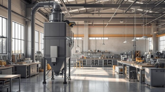
Key Components and Their Roles
A well-designed pulse-jet system balances airflow, pressure, and timing to ensure efficient operation. Its main components include:
- Filter Bags: Usually made of woven or non-woven materials like polyester or fiberglass, they trap fine particles while allowing air to pass through.
- Cages: Metal frameworks that support the filter bags, preventing collapse during cleaning cycles.
- Blow Tube and Nozzles: Deliver controlled pulses of compressed air into each bag row.
- Pulse Valves and Air Header: Control the timing and distribution of air pulses.
- Differential Pressure Sensor: Monitors pressure drop across filters to trigger cleaning cycles automatically.
- Hopper and Discharge Mechanism: Collect and expel the cleaned dust safely.
The synergy among these components determines the efficiency and lifespan of the collector.
Pulse-Jet Dust Collector Design Calculation & Sizing Sheet
| Parameter | Description / Formula | Typical Values / Notes |
| 1. Air-to-Cloth Ratio (A/C Ratio) | Volume of air passing through each square meter of filter area per minute. Formula: A/C = Q / A | – Range: 0.8–1.5 m³/m²/min – Lower A/C = better filtration but larger filter area required – Higher A/C = smaller system, higher pressure drop |
| 2. Filter Area (A) | Total filter area required for airflow. Formula: A = Q / (A/C) | Example: For Q = 10,000 m³/h and A/C = 1.2 m³/m²/min → A ≈ 139 m² |
| 3. Bag Diameter & Length | Determines the number of filter bags needed to reach total filter area. | – Diameter: 120–160 mm – Length: 2–6 m – Number of Bags: = Total Filter Area ÷ Area per Bag |
| 4. Pulse Pressure & Duration | Parameters for cleaning compressed-air pulses. | – Pressure: 0.5–0.7 MPa – Pulse Duration: 100–200 ms – Too high → bag damage – Too low → poor cleaning efficiency |
| 5. Dust Loading & Particle Size | Affects the required A/C ratio and cleaning frequency. | – Heavy/Sticky Dusts (cement, carbon black): lower A/C ratio, more frequent cleaning – Fine/Dry Dusts: higher A/C ratio acceptable |
| 6. Differential Pressure Monitoring | Used to trigger cleaning cycle automatically. | – Maintain within 1000–1500 Pa (typical range) for stable performance |
| 7. Hopper Discharge Rate | Depends on dust load and cleaning interval. | – Must be sized to avoid dust buildup or re-entrainment |
Quick Design Example
- Airflow (Q): 10,000 m³/h
- Selected A/C Ratio: 1.2 m³/m²/min
- Required Filter Area (A): 139 m²
- Filter Bag Size: 150 mm × 3 m
- Filter Area per Bag: 1.41 m²
- Total Bags Needed: ≈ 99 bags
Operational Best Practices
For optimal performance and a long filter life, it is important to maintain consistent operating conditions. The airflow through the system should remain stable, as sudden fluctuations can lead to uneven dust loading and reduced efficiency.
The compressed air used for cleaning must always be dry, since moisture can cause dust to stick to the filter bags and result in clogging.
Regular attention to the hopper is also essential; dust should be discharged frequently to prevent back pressure from building up inside the collector.
Routine maintenance plays a key role as well-inspect the filter bags for signs of wear or tearing, verify the accuracy of valve timing, and monitor differential pressure readings over time.
To ensure the system operates within environmental standards, it is advisable to use emission sensors or opacity monitors.
These devices provide valuable feedback and help maintain compliance while supporting clean and efficient plant operations.
Conclusion
The pulse jet dust collector remains the industry standard for effective particulate control thanks to its efficiency, durability, and ability to handle continuous processes.
Understanding its working principle, major components, and design calculations enables engineers and plant managers to select or optimize a system that ensures clean air, regulatory compliance, and long-term reliability.
Properly maintained, this technology provides years of dependable service while reducing environmental impact and operational costs.


")
